Unveiling the Image Rejection Ratio (IRR)
For any engineer working with radio frequency (RF) transceivers, a deep understanding of key performance metrics is paramount. One such critical parameter that directly impacts the quality and fidelity of a transmitted or received signal is the Image Rejection Ratio (IRR). It is also frequently referred to as Residual Sideband (RSB) suppression. This metric quantifies the modulator's ability to generate a clean single-sideband signal and suppress the unwanted sideband, or "image." A poor IRR in a transmitter can lead to spectral regrowth, interference with adjacent channels, and a violation of regulatory spectral masks. This blog post will delve into the concept of IRR from a transmitter's perspective, explaining its origin, its importance, and the methods used to analyze and calculate it in modern RF transceivers.
Basic Quadrature Error Analysis
Ideal Up Conversion
Modern RF transceivers extensively use quadrature modulators (also known as I/Q modulators) to efficiently impress information onto an RF carrier. The core idea is to modulate two orthogonal carriers—an in-phase (I) component, typically a cosine wave, and a quadrature (Q) component, a sine wave—with two independent baseband signals. When these modulated signals are summed, they create a single-sideband (SSB) or a complex modulated signal.
The ideal operation can be represented as:
Here, $I(t)$ and $Q(t)$ are the baseband message signals, and $\omega_{LO}$ is the carrier frequency.
To truly understand the up conversion, let's assume we want to transmit a single tone at a frequency $\omega_{BB}$ away from the carrier, so our baseband signals are $I(t) = \cos(\omega_{BB} t)$ and $Q(t) = \sin(\omega_{BB} t)$. This gives:
This ideally produce a single tone at $\omega_{LO} + \omega_{BB}$.
Mismatched Up Conversion
The two signal paths within the I/Q modulator inevitably suffer from slight differences. These imperfections are primarily:
- Amplitude Imbalance: The gain of the I-path and the Q-path are not perfectly identical. Assuming the gain of the Q-path is $(1+\epsilon)$ relative to the I-path.
- Phase Imbalance: The phase difference between the I and Q local oscillator (LO) signals is not exactly 90 degrees, assuming the error is $\theta$
These non-idealities corrupt the signal and cause energy to leak into the unwanted or "image" sideband at $\omega_{LO} - \omega_{BB}$, degrading the modulator's performance. The IRR (or RSB) is the measure of how well the modulator suppresses this unwanted image sideband relative to the desired signal sideband.
We can write the output of the impaired modulator by introducing the imbalances into the ideal equation. The LO signals for the I and Q paths become $\cos(\omega_{LO} t)$ and $-(1+\epsilon)\sin(\omega_{LO} t + \theta)$, respectively. The output signal is:
where $\Sigma=\omega_{LO}+\omega_{BB}$ and $\Delta=\omega_{LO}-\omega_{BB}$ for simplification.
Let’s take squares of these tones since we are interested in ratios of their powers. Since $|a\cos(x)+b\cos(x+\theta)|=a^2+b^2+2ab\cos(\theta)$, we have:
- $|\Sigma \mathrm{tone}|^2=\frac{1}{4}\left[(1+\epsilon)^2+2(1+\epsilon)\cos(\theta)+1\right]$
- $|\Delta \mathrm{tone}|^2=\frac{1}{4}\left[(1+\epsilon)^2-2(1+\epsilon)\cos(\theta)+1\right]$
Therefore the IRR is calculated as
Note that $\theta$ is in radians.
Ideal Down Conversion
At the receiver side, we can recover the baseband I and Q signals through down conversion IQ modulator. If we write the received RF signal as the sum of I and Q path up-converted signals. The down-conversion modulator I path output signal can be expressed as
where $LPF\{x(t)\}$ denotes the low-pass function on signal $x(t)$ to filter out everything above the signal bandwidth. This $I_{demod}(t)$ is exactly a scaled version of original I-path signal.
Similarly for the Q path, we have
This is also a scaled version of original Q path signal, which proves the correctness of the down-conversion process.
In another point of view, we can write the received RF signal as the sum of upper side band (USB) signal $A_U\cos[(\omega_{LO}+\omega_{BB})t+\phi_U]$ and lower sideband (LSB) signal $A_L\cos[(\omega_{LO}-\omega_{BB})t+\phi_L]$, then the down conversion process would be
Similarly for the Q path
Then the upper and lower sideband signals can be recovered through Hilbert conversion.
If we define the upper and lower BB signal as
The Hilbert transform, denoted as $\mathcal{H}\{x(t)\}$, is a linear operator that shifts the phase of every frequency component of a signal by -90° (or -π/2 radians). For a cosine wave, its effect is:
Using this property, we can express the Q(t) signal in terms of the Hilbert transforms of our baseband USB and LSB signals:
Substituting these into the equation for Q(t) gives:
A crucial property of the Hilbert transform is that applying it twice inverts the original signal:
To recover the USB and LSB signal, the key step is to apply the Hilbert transform to the entire Q equation.
Mismatched Down Conversion
We can write the output of the impaired modulator by introducing the imbalances into the ideal equation. The LO signals for the I and Q paths become $\cos(\omega_{LO} t)$ and $(1+\epsilon)\sin(\omega_{LO} t + \theta)$, respectively. The output signal for I path is unchanged, but for Q path, it is:
Then the recovered USB signal is
Similarly, we can calculate IRR as
Quadrature Error Analysis with Complex Baseband
Ideal Up Conversion
This is arguably the most elegant and powerful method, widely used in digital signal processing. We represent the baseband signal as a complex number $s(t) = I(t) + jQ(t)$. An ideal SSB signal is generated by multiplying this complex baseband signal with a complex exponential carrier $e^{j\omega_{LO} t}$:
This perfectly matches the ideal modulator equation.
Another way to understand the complex baseband is through frequency shifting. Multiplying $e^{j\omega_{LO} t}$ in the time domain is equivalent to shift the spectrum to the right side by $\omega_{LO}$. Taking the real part out of a complex signal is equivalent to
This means the positive spectrum's conjugate is copied to the negative frequency.
Mismatched Up Conversion
The I/Q imbalance can be modeled as two complex gains, $K_1$ and $K_2$, that operate on the ideal signal and its complex conjugate (which represents the image). The actual transmitted complex baseband signal, $s'(t)$, can be written as:
where $s^*(t) = I(t) - jQ(t)$ is the complex conjugate.
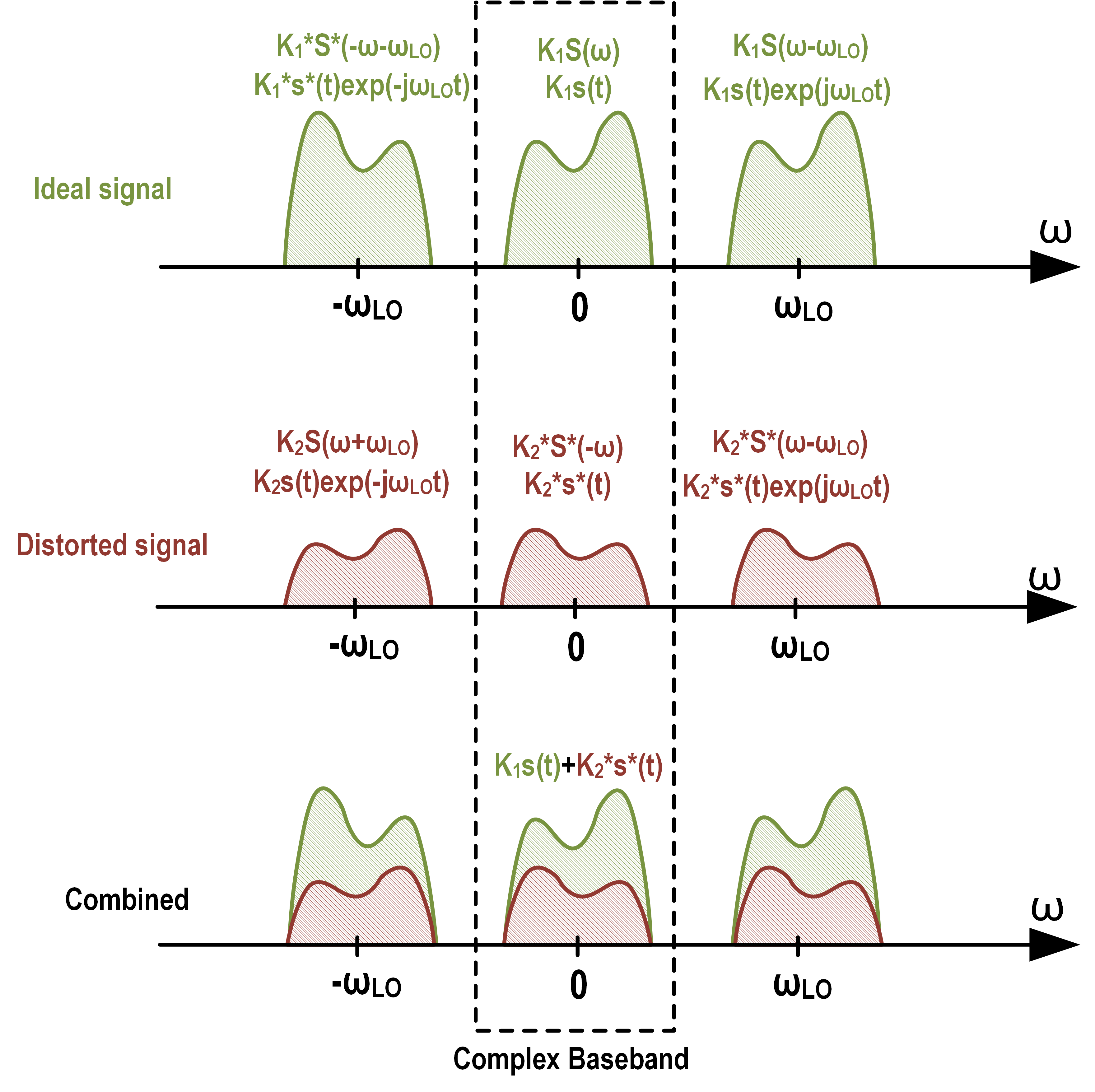
The coefficient $K_1$ represents the gain for the desired signal, and $K_2$ represents the gain for the image signal.
Starting from the RF signal with mismatch
Then the mismatch can be treated as a distortion in the baseband signal as
We can also organize the complex distorted signal as
which leads to
The solution is therefore
The Image Rejection Ratio is simply the ratio of the power of the desired term to the power of the image term
This complex method is highly efficient as it directly provides the gains for the signal and image paths, making the analysis and simulation of I/Q imbalance correction algorithms much more straightforward.
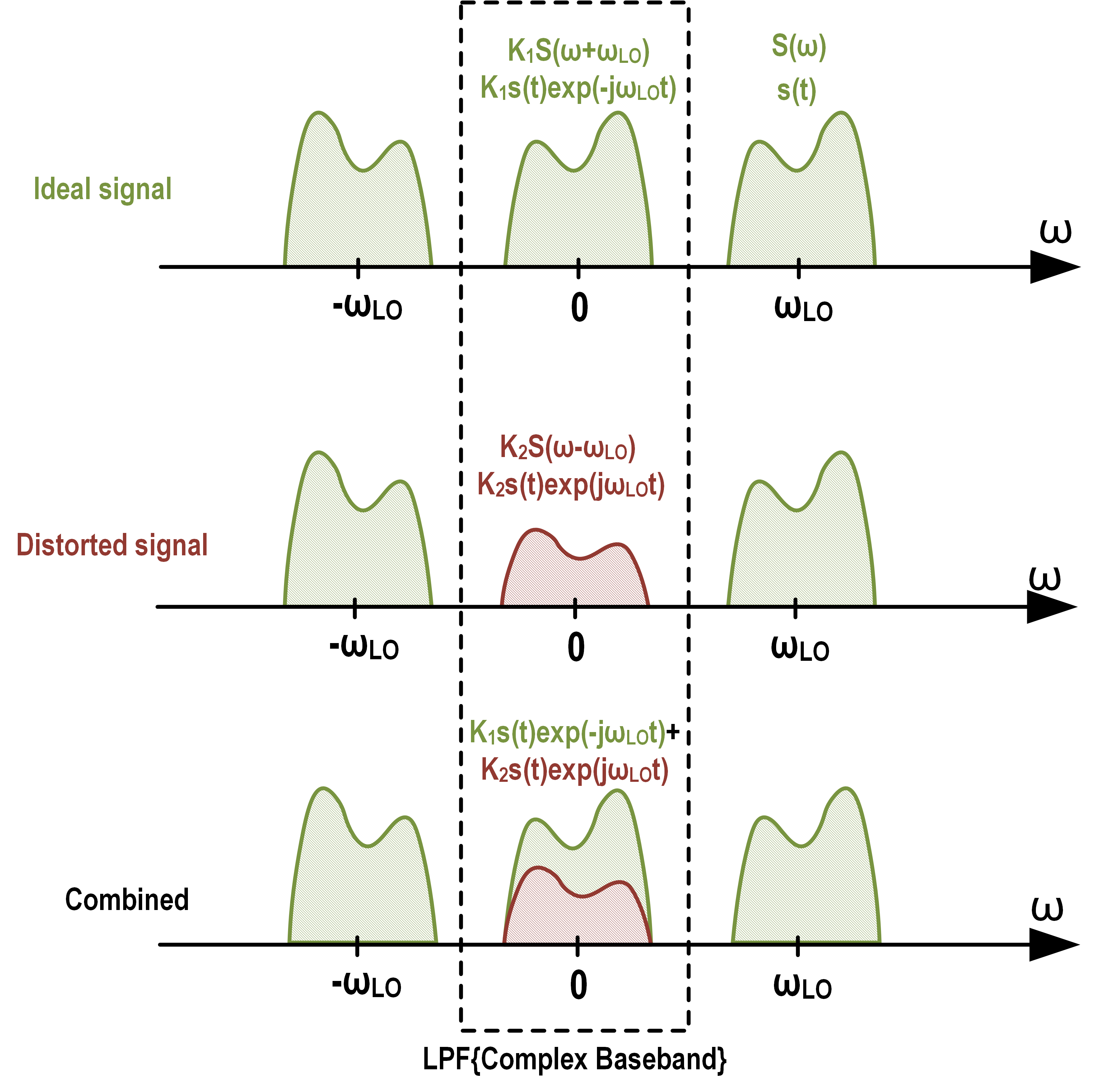
Ideal Down Conversion
We represent the baseband signal as a complex number $s_{RX}(t) = I(t) + jQ(t)$. An ideal SSB signal is generated by multiplying this complex baseband signal with a complex exponential carrier $e^{j\omega_{LO} t}$:
Mismatched Down Conversion
Adding mismatch, the equation becomes
IRR Calibration
TX IRR Calibration
TBD
RX IRR Calibration
TBD
Joint-TRX IRR Calibration
TBD
References
- RF Insights, “IQ Calibration,” RFIC Design. Available: https://www.rfinsights.com/insights/measurements/calibration/iq-calibration/
- B. Razavi, RF Microelectronics, 2nd ed. Upper Saddle River, NJ: Prentice Hall, 2012, pg. 205-209.
- W. Al-Qaq, R. L. Bunch, D. Mahoney, and P. Brey, “Transceiver IQ calibration system and associated method,” US9025645B2, May 05, 2015. [Online]. Available: https://patents.google.com/patent/US9025645B2/en
- W. Al-Qaq, “Transmitter image calibration using phase shift estimation,” US11533113B2, Dec. 20, 2022 [Online]. Available: https://patents.google.com/patent/US11533113B2/en
- Post link: https://triblemany.github.io/archives/f36a953b/irr.html
- Copyright Notice: All articles in this blog are licensed under BY-NC-SA unless stating additionally.