Class D Power Amplifier
This article intends to cover basic concepts of switching mode power amplifier, and the design of class D power amplifier.
Simple Switching Amplifier

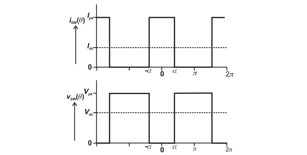
where we have
As for the fundamental components
Mathematica code for Fourier series
1 | f[x_] := Piecewise[{{0, -a <= x <= a}, {1, x < -a}, {1, x > a}}] |
Hence, we can calculate the efficiency as
To compare with the class A PA, we write the output power as
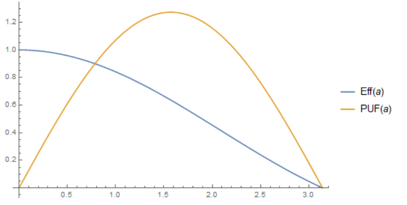
We can plot the efficiency and PUF vs. conduction angle
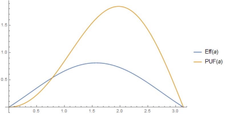
1 | Eff[a_] := 2 Sin[a]^2/a/(Pi - a); |
The peak power occurs at a conduction angle of around 113 degrees. Though the structure dissipate no heat, the peak efficiency is about 81%, as some of the power is wasted in harmonic components.
Switching Amplifier with Harmonic Short
To remove harmonic components, we can place a harmonic short across the load.
In this case, the voltage waveform must assume a sinusoidal form.
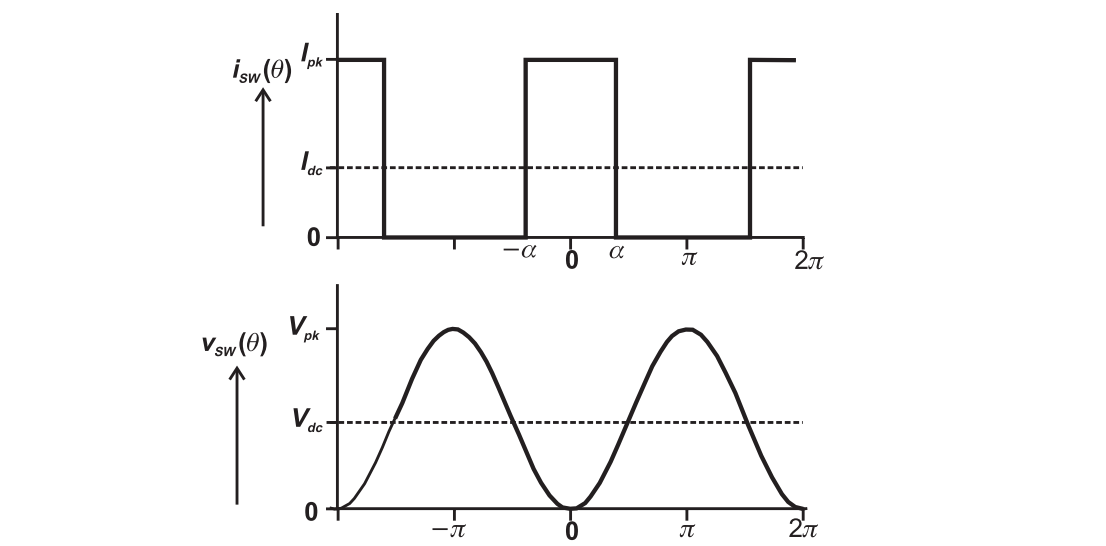
Repeat the analysis, we have
It can be plotted as
1 | Eff[a_] := Sin[a]/a; |
The peak power occurs at a conduction angle of 90 degrees with an efficiency of 63 %.
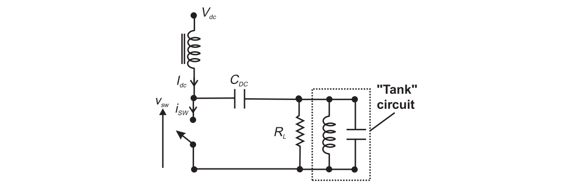
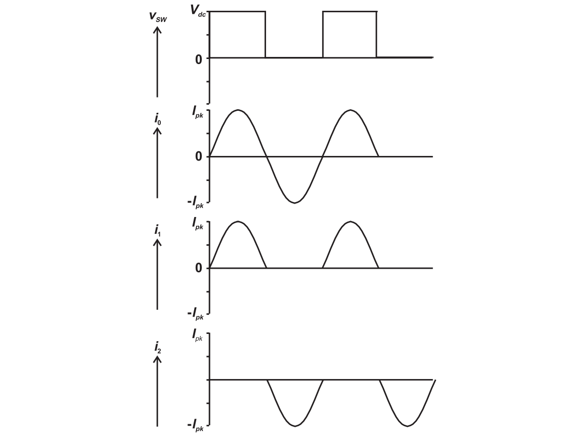
Class D Power Amplifier
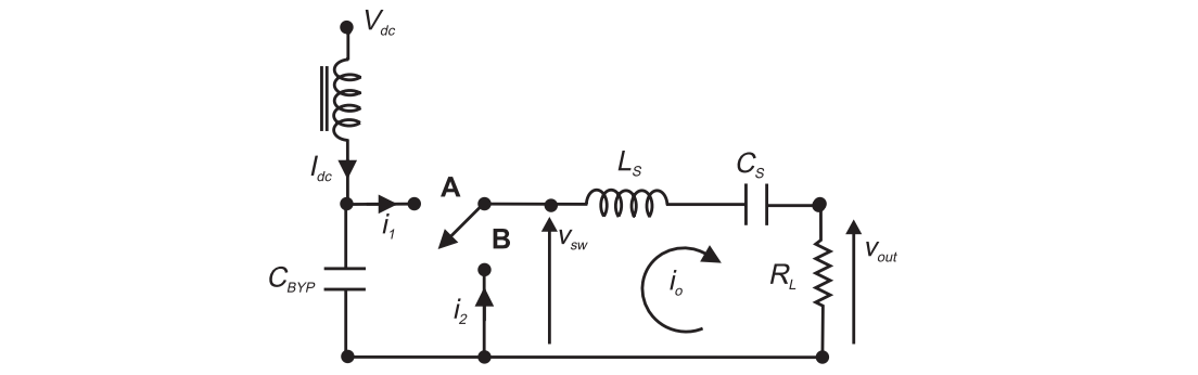
The key point is that the current in the LCR branch is constrained to remain sinusoidal. With a sufficiently large bypass capacitor, the voltage $v_{sw}$ would remain $V_{dc}$ when the switch is turned to A, and remain zero when turned to B.
We have
It can achieve theoretically 100 % efficiency with 1 dB higher power than class A amplifier.
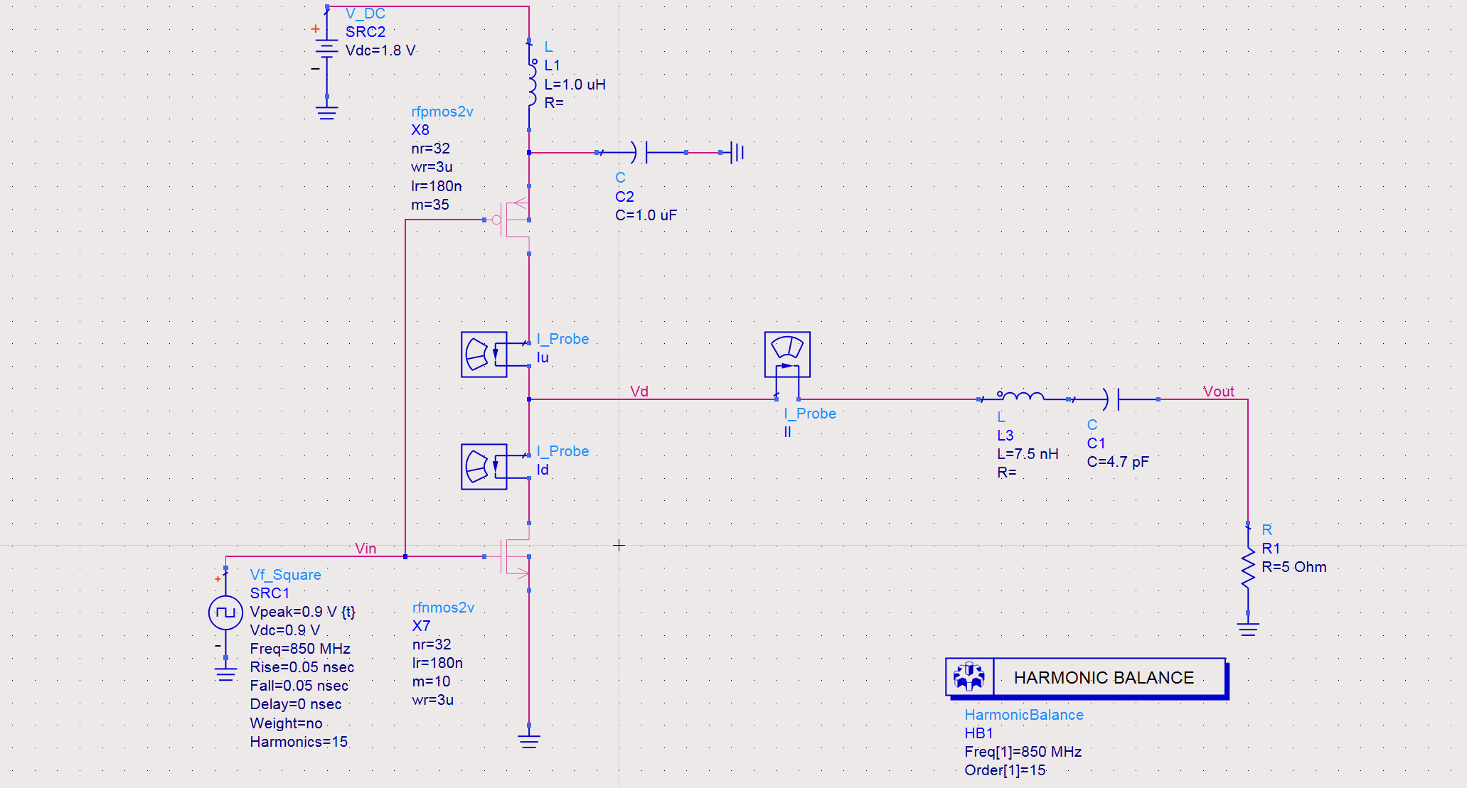
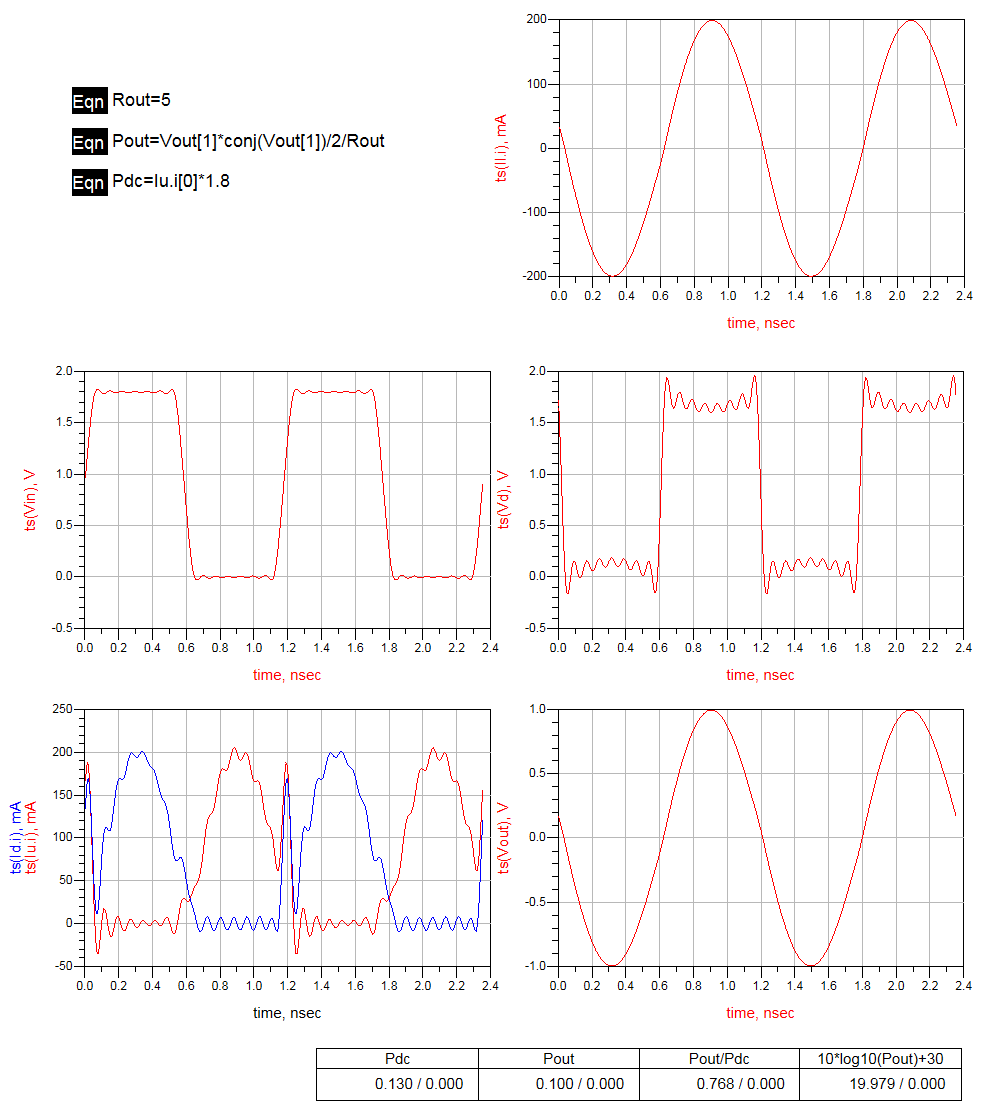
A realization
Reference
- S. C. Cripps. RF Power Amplifier for Wireless Communications. Artech House, 2014.
- Post link: https://triblemany.github.io/archives/358f72b0/class-d-power-amplifier.html
- Copyright Notice: All articles in this blog are licensed under BY-NC-SA unless stating additionally.